What is YARE ?
Fourth Year Project
Every student in computer engineering at the University of Ottawa is required to participate to a fourth year project to complete their degree. In the particular project class I attended, a computer design problem was to be solved in groups of six people. All of the proposed problems involved controlling a robot through an environment. YARE is the named that we gave to our robot.
The proposed projects were varied. One required a robot to follow a line on the ground and avoid obstacles. One required a robot to receive a path drawn on a PDA and move along said path. The project we chose had the following requirements:
“A mobile robot controlled by the Altera UP-2 board and/or the HC12 microprocessor will have to traverse a maze-based map in order to get from one end to the other of the maze. The main objective is to utilize remotely-embedded knowledge to solve the task at hand. IR sensors should be used to locate the openings within the maze, while a wireless communications scheme should be utilized to communicate with the knowledge base residing on a remote PC. A lookup table may be initially used, but as the task gets more complicated, a knowledge base should be utilized. The autonomous mobile robotic platform will acquire and interpret the data, in accordance with the remotely-embedded knowledge, and can update the knowledge base with newly learnt factoids. Contacts sensors should be used for handling accidental collision situations.”
In other words, we had to design a robot that would find the shortest path in a maze. This involved having the robot autonomously traverse the maze, wirelessly communicate its recorded data to a base station, process that data to find the shortest path and finally control the robot through the shortest path. Our team consisted of the following people, all soon-to-be computer engineers:
- Dominic Bergeron
- Georges Daoud
- Bruno Daoust
- Erick Duchesneau
- Mathieu Mallet
- Martin Hurtubise
Initial Design
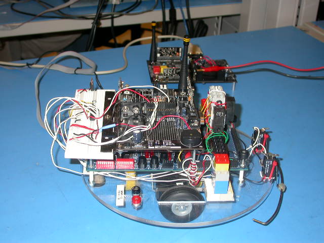
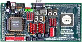
Before starting work on the project, we needed to know what had to be done. The only things provided to us were the requirements and a plexiglas board on which were mounted and Altera UP-2 board, two servos with wheels and a Linx HP-II wireless prototype board. Though most of the components were already mounted, interfacing them to each other was left to us. Here were the tasks that we needed to perform:
- Hardware
- Mount and interface infra-red sensors
- Interface servos with Altera board
- Interface wireless prototype board with Altera board
- Software (Robot, in VHDL)
- Controller for servos and infra-red sensors
- Wireless receiver and transmitter controller
- Control algorithm to allow robot to navigate the maze
- Software (PC, in Java)
- Wireless receiver and transmitter interface
- Data decoder
- Data analyzer and shortest path algorithm
- Graphical User Interface (GUI)
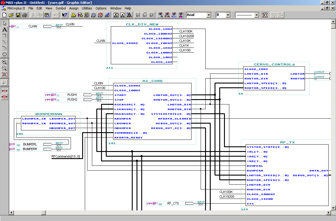
Software for the robot evidently needed to be written in VHDL as MaxPlus II was the tool available to write and load software onto the Altera board. We chose to write the software for the PC in Java as this is the language with which most people in our group had experience with. Tasks were then divided. Bruno started work on the algorithm that would be used to find the shortest path in the maze. Dominic started research on what would be needed to get the robot and the PC to communicate wirelessly. The rest of us started work on the hardware portion of the project.
First Steps
The first task was to interface the servos to the Altera board. Though connection is relatively simple (only three wires per servo -- power, ground and data), we had difficulty getting the software on the robot to generate the required PWM signals. This was due to the fact that previously taken VHDL classes had been rather simplistic and had only touched the surface of what was needed.

Interfacing the sensors proved to be much easier than interfacing the servos, partially because we were getting comfortable with the language but especially because free 'IP Core' were made available that would decode the signals generated by the sensors into semi-intellegible signals. Because the sensors have a 10cm 'dead zone' in which the signals cannot be trusted (e.g. the sensor would detect '90 cm' while the actual distance would be 5 cm), we decided to mount the sensors at the middle of the robot. However, the Altera board was located at the middle, we could not simply affix the sensors to the plexiglas. The solution to this proved to be elegant and efficient: we used legos to create a structure on which the sensors could be mounted.
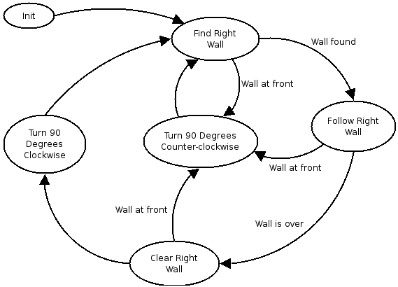
Once sensors and servos were working, getting the robot to navigate the maze was a trivial task. I wrote a state machine that would follow the algorithm illustrated on the picture to the left. The 'follow the right wall' algorithm would effectively guarantee that the robot would find the exit of the maze. Of course, there were problems: try as we might, we could not get the robot to go in a perfectly straight line. How could we insure that the robot does not diverge from the wall it's following? In the 'follow right' state, I added a few lines of code that would make the robot turn slightly if it came too close or went too far away from the wall. This simple compensation worked remarkably well once we found the proper distances to use in the algorithm. Those distances were found in a trial-and-error fashion. We now had a robot that could find the exit of a maze autonomously.
However, as we would soon find out, getting the robot to navigate the maze would be the easy part.
Wireless Troubles
For this project, we were required to transmit maze data from the robot to the PC, have the PC analyze the data and then control the robot through the maze, following the shortest path. Though the first part only requires a one-way communication, the second requires the PC to be able to send commands to the robot while receiving feedback from it. We therefore needed to find out how to use the boards in full-duplex mode.
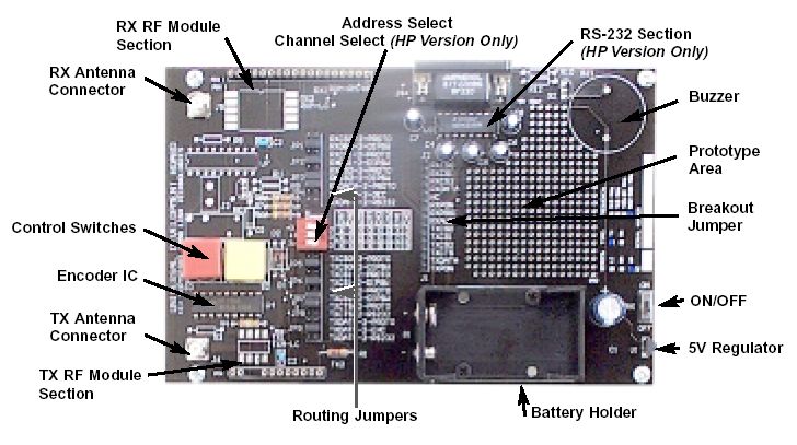
Included on the prototype boards is a set of DIP switches that can be used to set the incoming or outgoing signal channel. Reading through the board's documentation, we found that we could also use the jumpers to set the channel of the other signal (outgoing or incoming). Getting bi-directional communication was therefore a simple matter of choosing two channels to perform communications on.
One problem that we had using the wireless prototype boards was the heavy interference in the laboratory. There were about 11 other groups working in the same room, half of which used RF communications of some kind. For the longest time we couldn't get any signal to be received on the computer, until we can to the laboratory one week-end when no-one was there and discovered that interference was the cause of the problem. A second problem that we had was the reception of the data on the computer: to connect the RF board to the computer, a serial connection was used. However, on the robot the RF board was connected directly without using serial communications. Though we thought data received by the board would be encapsulated in serial packets before being sent to the computer, it was not. It took much debugging with oscilloscopes to realize this. We then wrote a VHDL module for the robot that would take the data that we wanted to send, encode it in 7-bits long serial packets and send it to the computer. Since the data was already in a serial format, the computer would then be able to read it from the serial port. For a complete description of the protocols used, refer to the project report at the end of this page.
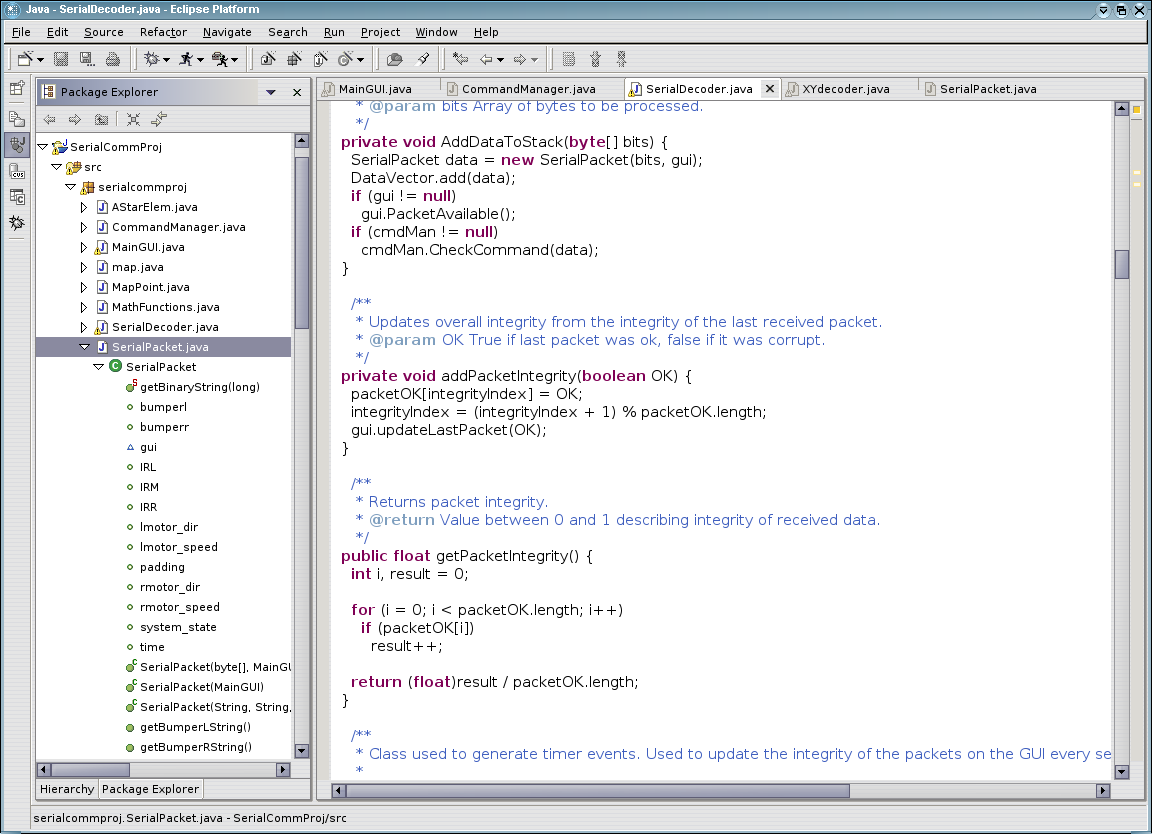
Java Interface
While the robot's RF communication modules were being written, I started work on the program that would be used to receive and process the robot's data as well as control it once the shortest path had been computed. Initially the program consisted of a few simple controls as well as a few threads to receive and decode the serial data received. Since the computer needed to decode the data sent by the robot, work was done on both the robot's modules and the computer's software simultaneously. The biggest problem encountered was the manipulation of bit data in Java: while trying to read bytes from the serial interface, Java would always use signed variables and skew the data. Finally, we got the reception and decoding working as well as the error detection.
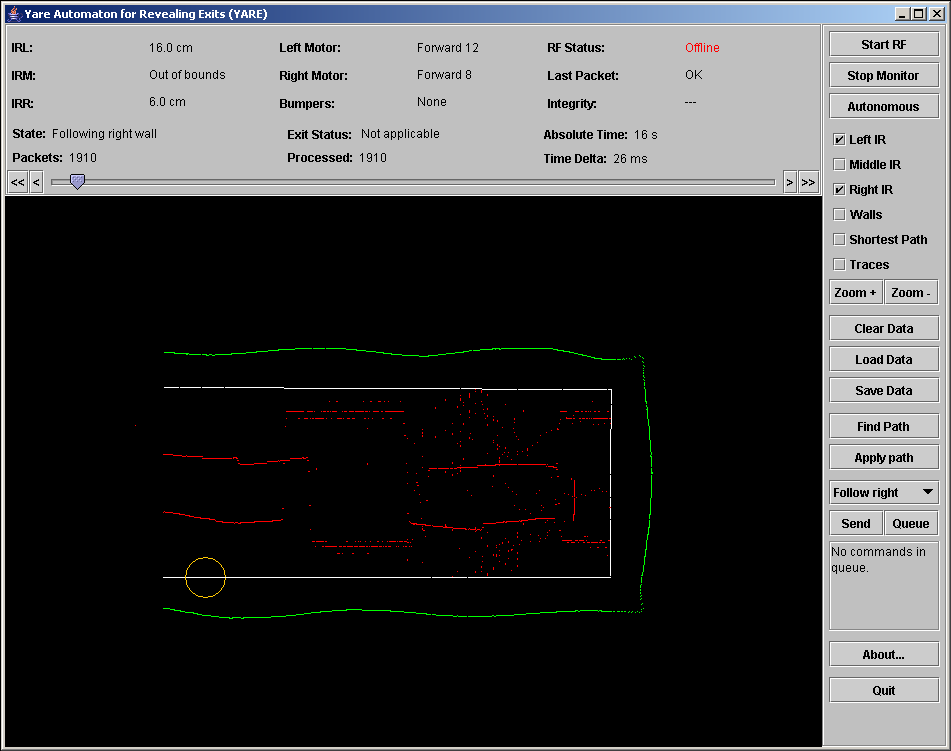
Once RF communications were working, we wrote a simple routine that would take the decoded data and plot it on screen. This allowed us to get a real-time representation of what the robot was seeing as it went through the maze. Though this was relatively simple, the much harder task of making sense of that data and finding the shortest path awaited us.
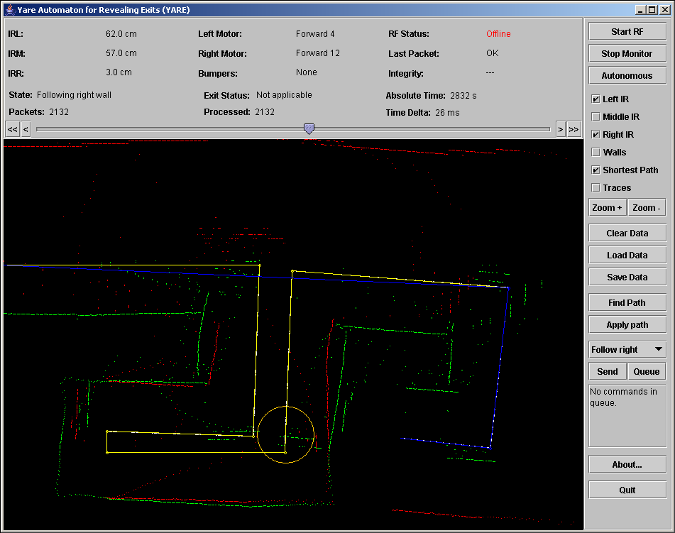
As mentioned earlier, Bruno started to work on the maze-solving algorithm early in the project. Though the algorithm worked very well using theoretical values (vertices of walls and points at which the robot could move), the data we had was merely a collection of recorded data points. Erick wrote a thread that would take my decoded data and extrude 'simple' walls from it. Getting the routine to work correctly, even with the occasional 'hiccups' from the sensors, required long weekends of work. An example of the wall-detection algorithm in action can be seen by comparing this picture, which shows captured data points, with this picture, which shows the detected walls.. When we finally got the walls-detection algorithms as well as the shortest path algorithm working, we came to realize something: we could not tell the robot to follow the path that was found!
From the beginning, the robot was designed to simply follow walls. When following the shortest path, we sometimes required the robot to turn before the end of the wall was reached. How would the robot know when to turn? Erick came up with the solution: by having the program look at the next turn that the robot would have to perform, we could set the robot to always follow a wall and switch its following to the opposite wall when required. (See the video at the end of this document if this isn't clear)
Presentation and Demo
Once the project was completed, we needed to present it in front of our teachers and peers. Having worked on the project up till the last moment, time to prepare for the presentation was short. Nevertheless, we did two rehearsals and were ready. The presentation went quite smoothly, everyone knowing precisely which part they were to explain.
The demonstration is the part of the project that we were most nervous about. We only had one chance to demonstrate our robot's abilities: if some kind of malfunction was to occur, we would not be able to rectify it. Nevertheless, the demonstration went perfectly: the robot traversed the maze, the computer correctly processed the data and controlled the robot through the shortest path. You can see the video of the demonstration at the end of this document.
In conclusion, I think YARE was the most interesting project to which I took part. Though we had to put more work in this one class than we usually did in an entire semester, I believe that the experience that it gave us will help us for years to come.
Additional Documents
A few screen shots of the YARE interface: 1 2 3 4
The final report documenting the design of YARE
Power point slides used during project presentation
Video of the demonstration (7.7 MB, xvid codec required)
YARE Java client: download (1.3 MB) or launch with Java Webstart (webstart version cannot open or save files however)